Preparing DXF contour

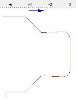
The DXF path has to be prepared in a way that:
- The wire is clear from PCD and tool body at the end points of the contour
- The X-coordinate of contour start point and end point is not identical, because the software has to determine the “main profile direction” (blue arrow) from the difference of X-start-point and X-end-point
Determining the “machining mode”

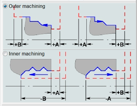
Due to the detected “main profile direction” (blue arrow), with the above
contour example, the situation fits to the upper right sketch in the
profile window. This means “Outer machining” has to be selected in this
situation.

With this selection the relief angles on the outer contour section will be
applied according to the general settings. But for the inner contour
section the radial relief angle has to be applied in opposite direction.
To enable this, the checkbox “Angle valid for entire profile” has to be
unchecked.
Edit individual angles

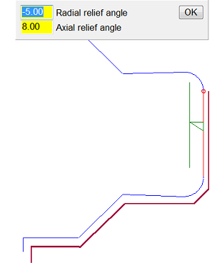
With the setting above the button “Edit individual angles” can be used to
open the geometry window for setting individual relief angles for each
contour element. In this window each contour element of the inner
contour section (beginning with the vertical line on the front end) has
to be identified and a suitable negative “Radial relief angle” has to be
assigned.
Setting the “Backw. Path B”
For a “collision free” escape from the inner contour end point the “Backw. path” has to be extended. With this setting the machine will move 8mm in X-direction before moving in Y-direction (Purple lines in simulation) .
The simulation also shows the correct change to the negative radial relief for the inner contour section

