Info
This value is only available/important for wire EDM versions of ProfDia/Exprog!
After doing the machine setup GTR recommends to do a double-U test cut. With this test cut the correct Z-height will be determined for programming. Maintaining inaccuracy after the setup can be compensated.
Info
Wrong Z values impact the cuttig result for axial angle tools and axial free angle tools negatively.
For the test cut you have to do a DXF-drawing with correct values.

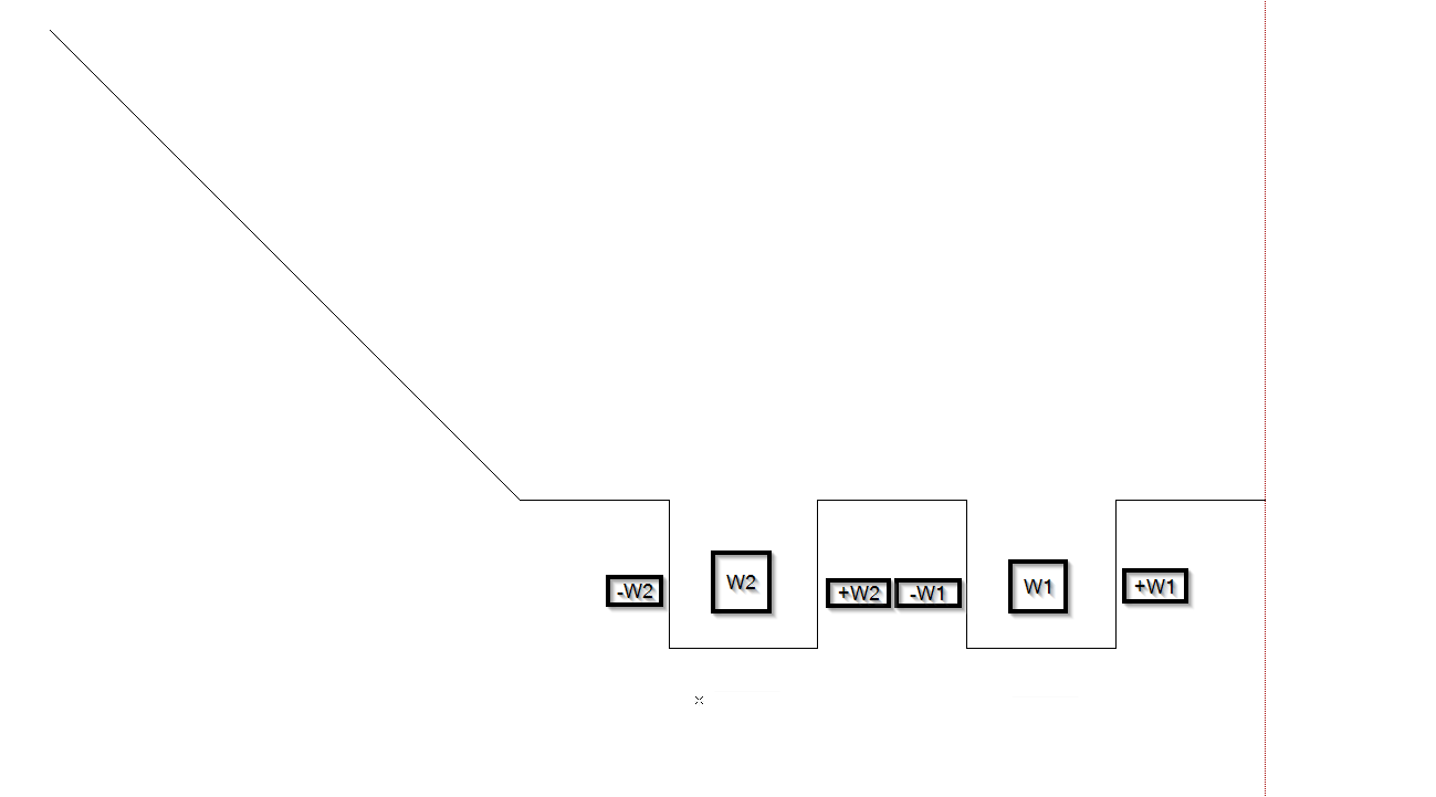
The profile has to be drawn like in the picture above. At the end of the profile (left side) is just a move away movement to ensure, that the cut out material falls apart. The profile has to be drawn on the correct tool-radius (orientation to existing test plate). If the test cut has to be repeated, it is possible to set a diameter offset.
Danger
The offset value refers to the diameter not the radius

The dimensions of the test cut are quite simple. The edge lengths are always 1mm. If necessary (thicker material) the edge lengths can also be increased with consultating GTR. The test cut inerits axial angles and radial angles.
Settings for the subcontour:
- Select axial angles as given
- deactivate Angles valid for entire contour
- Save subcontour
- Via the button Adjust single angle set the angles as given
Set the radial angles continuously at 8.0°.
Program the axial angles as follows:
- W1: 0.5°
- W2: 8.0°
The sign of the angles are shown in the drawing above. If you have bigger axial angles, you can ernlarge W2. GTR recommends the angles as stated above. If the test cut is finished, measure B2 and B2 and insert the values in the corresponding input fields in the toolbox.
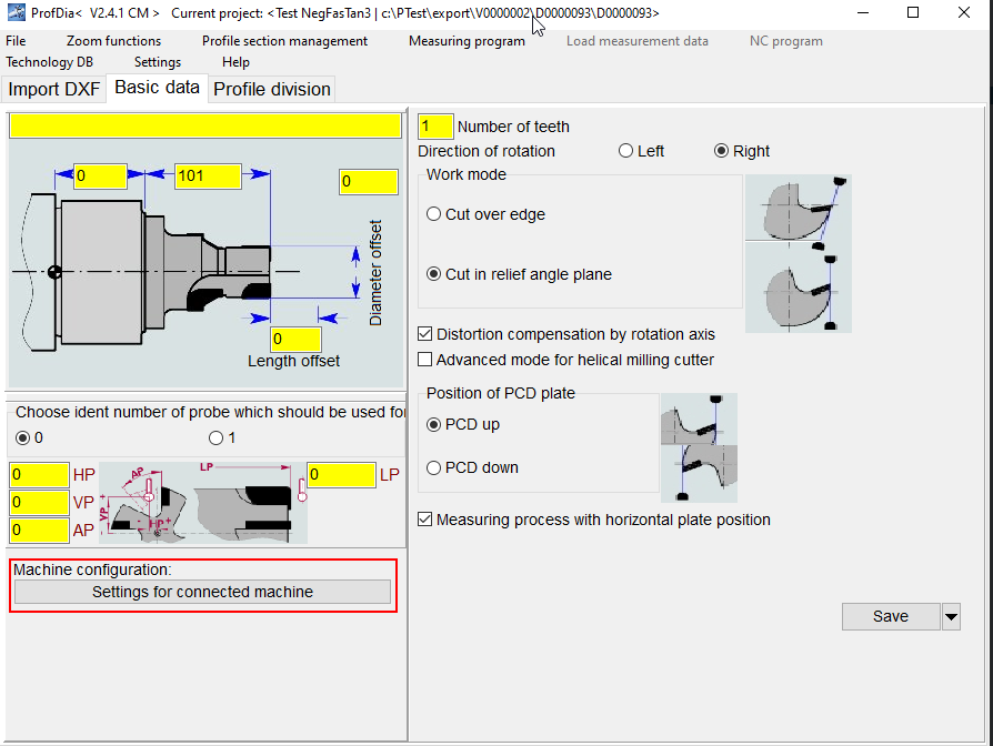
Additionally you have to select, whether the PCD surface is up or down aligned.
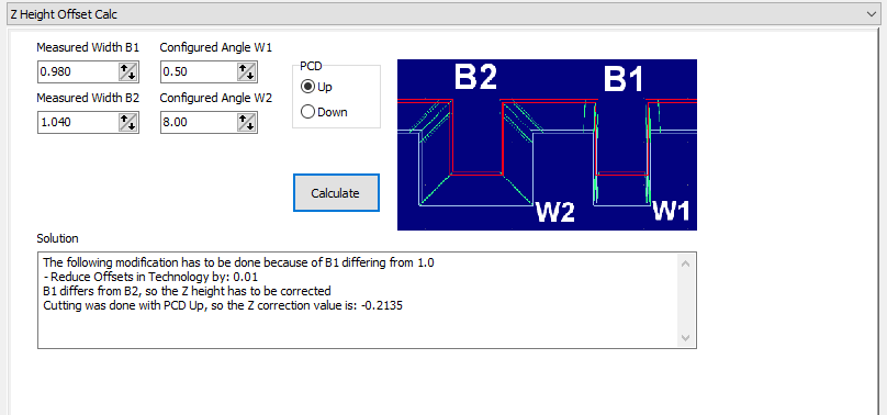
After the values are inserted, click calculate. The software now is calculating the Z-height offset and also a correction value for the wire offset. The Z hieght correction has to be set now in ProfDia. Start ProfDia and click Setings for connected machine.
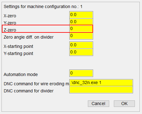
In the small window insert the calculated value at Z-zero.
If value B1 is measured B1 <> 1mm, the ProfDia toolbox calculates a correction value for the wire offsets. This offsets have to be set at the relevant technologies.
After inserting Z-zero, re-do the test cut and measure B1 and B2 again. The widths B1 and B2 should now be similar to 1mm. If you are unsurea about the result feel free to contact us.
Info
Are the widths after a repeated test cut still different, then there is a problem with the principal setting of the connected machine. In this case we recommend you to to do a complete alignment incl. zero point setup
- Check all relevant components for wear and correct installation (wire guides, …)
- Straighten the wire
- Determine wire deflection points
- Set Z-zero to 0
- Re-do the test cut